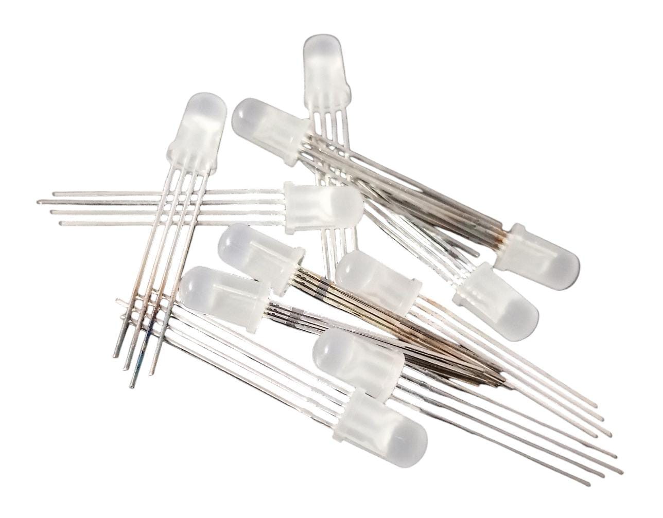
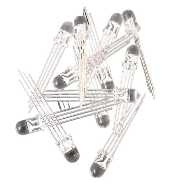
5mm Round RGB LED: A Detailed Overview
The Common Cathode LED configuration features shared cathodes and individual anodes, with a forward voltage range of 3.3 to 5 volts, ensuring compatibility with different power sources. Rated for a reverse current of 50µA and a continuous forward current of 20mA, it offers protection and reliability. With a 5mm diameter and 4-pin design, it suits indicator lights, displays, and automotive lighting. Operating from -40 to 85°C, it’s adaptable to various environments, promising robust performance in diverse applications.
Specifications
| Parameter | Value |
|---|---|
| LED Configuration | Common Cathode |
| Forward Voltage | 3.3 ~ 5V |
| Reverse Current | 50µA |
| Continuous Forward Current | 20mA |
| Power Dissipation | 100mW |
| LED Diameter | 5mm |
| Number of Pins | 4 |
| Operating Temperature | -40 ~ 85°C |
| Mounting Type | Through Hole |
Features
- Tri-color Design: Combines red, green, and blue LEDs in a single package, allowing for the emission of a wide range of colors.
- Common Cathode Configuration: Simplifies circuit design by providing a shared cathode pin for all three colors.
- Standard 5mm Round Package: Fits into standard 5mm round LED mounting holes, ensuring compatibility with existing designs and equipment.
- High Brightness: Each color LED chip offers high luminous intensity for vibrant and visible illumination.
- Wide Viewing Angle: Provides a viewing angle of 120 degrees, ensuring uniform illumination across a broad area.
- Low Power Consumption: Operates at a low forward current, making it energy-efficient and suitable for battery-powered applications.
- Durable Construction: Designed to withstand a wide range of temperatures and environmental conditions, ensuring long-term reliability.
- Lead-Free and RoHS Compliant: Manufactured using lead-free materials and compliant with RoHS environmental standards, minimizing environmental impact.
Applications
- Decorative Lighting: Used in signage, displays, and architectural lighting to create dynamic and colorful effects.
- Indicators and Displays: Employed in electronic devices, control panels, and appliances to indicate status, mode, or function.
- Entertainment Systems: Integrated into stage lighting, DJ equipment, and audiovisual displays for dynamic lighting effects.
- Automotive Lighting: Installed in automotive interiors and exteriors for mood lighting, accent lighting, and decorative purposes.
- Gaming Peripherals: Used in gaming keyboards, mice, and controllers to add customizable RGB lighting effects.
- DIY Electronics Projects: Popular among hobbyists and makers for creating custom lighting projects, artwork, and interactive installations.
- Consumer Electronics: Incorporated into consumer electronics such as smartphones, laptops, and wearables for notifications and aesthetic enhancements.
Developments
Advancements in RGB LED technology continue to enhance performance, efficiency, and functionality:
- Miniaturization: Shrinking the size of RGB LEDs for use in compact devices and applications with limited space.
- High-Density Arrays: Developing RGB LED arrays with multiple LEDs integrated into a single package for higher brightness and more intricate lighting effects.
- Smart RGB LEDs: Integrating control circuitry and communication interfaces into RGB LED packages for programmable lighting effects and synchronization.
- Improved Color Accuracy: Enhancing color reproduction and accuracy through advancements in LED chip design and phosphor materials.
- Efficiency Improvements: Increasing luminous efficacy and reducing power consumption through improvements in LED chip efficiency and thermal management.
Instructions for Use
- Polarity Identification:
- Identify the common cathode pin (usually the longest pin or labeled as “C”) and connect it to the ground (GND) of the circuit.
- Connect the anode pins of each color (red, green, blue) to the respective output pins of the driving circuit.
- Current Limiting Resistors:
- Use current-limiting resistors in series with each LED color to ensure that the forward current does not exceed the specified maximum rating (typically 20mA per color).
- Calculate the appropriate resistor value using Ohm’s Law based on the supply voltage and LED forward voltage.
- Circuit Design:
- Design the driving circuit to provide the required forward voltage and current for each LED color.
- Ensure proper heat sinking and thermal management to prevent overheating of the LEDs and prolong their lifespan.
- Mounting:
- Insert the LED into the mounting holes on the PCB, ensuring that the polarity is correct.
- Bend the leads slightly to secure the LED in place before soldering.
- Soldering:
- Solder the leads of the LED to the PCB pads using a soldering iron and solder wire.
- Avoid excessive heat and soldering time to prevent damage to the LED.
- Testing:
- Test the RGB LED using a suitable power supply and driving circuit to verify proper operation and color mixing.
- Check for uniform brightness and color consistency across all LED colors.
- Integration:
- Integrate the RGB LED into the final product or assembly, ensuring that it is securely mounted and electrically connected.
- Test the functionality of the RGB LED within the context of the overall system or application.
Conclusion
The 5mm Round RGB LED with a common cathode configuration offers a versatile and customizable lighting solution for various electronic applications. Its tri-color design, standard package size, and through-hole mounting make it easy to integrate into both new and existing designs. Ongoing advancements in RGB LED technology continue to drive improvements in performance, efficiency, and functionality, expanding the possibilities for dynamic and vibrant lighting effects in a wide range of applications. Proper circuit design, soldering techniques, and testing procedures are essential to ensure optimal performance and longevity of RGB LEDs in electronic designs.
For more related products: Click here
For more services: Click here

Reviews
There are no reviews yet.