4-20mA to 5V Converter for Arduino Industrial Sensor Interface Board: An Overview
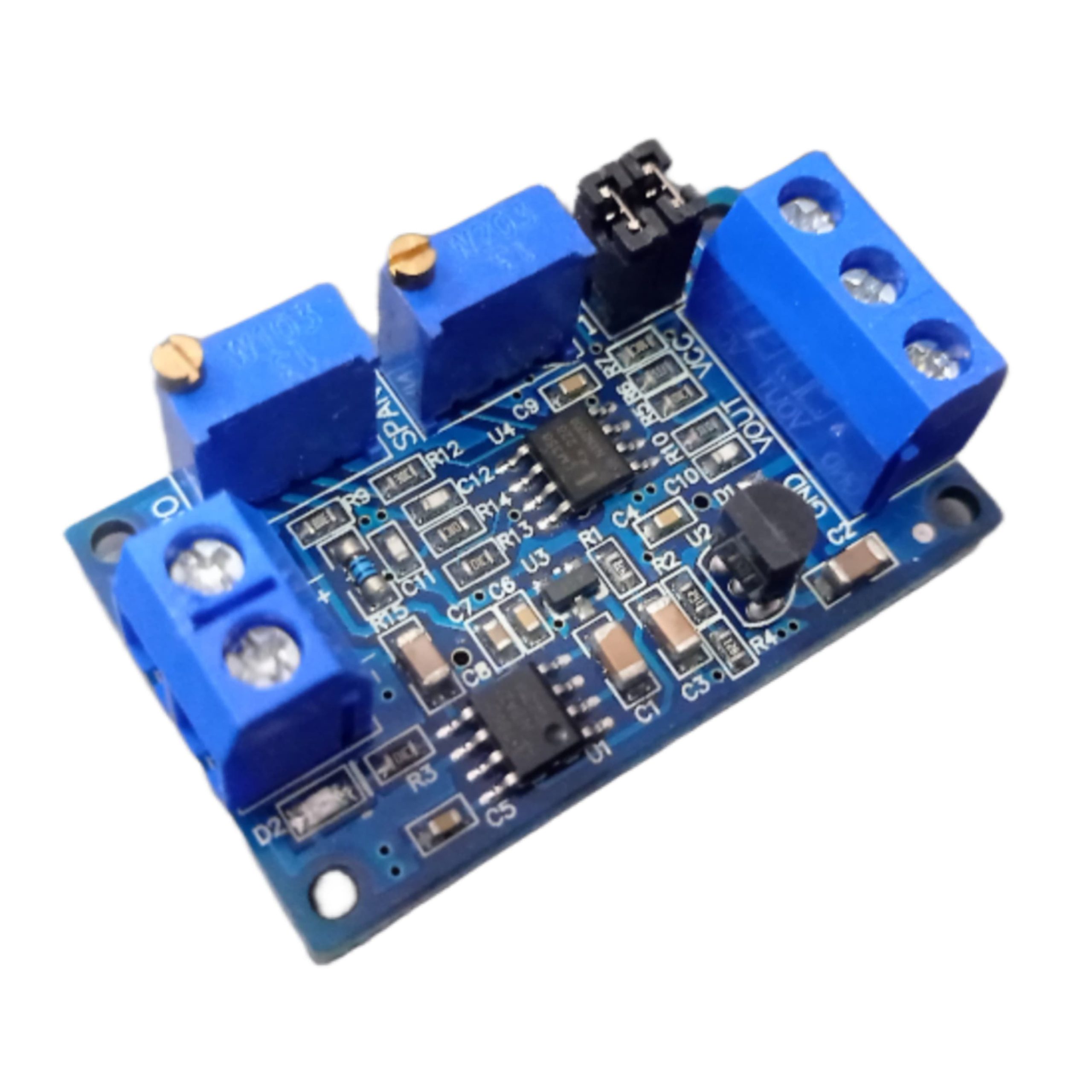
4-20mA to 5V Converter This module lets you interface your Arduino/Raspberry Pi or any other microcontroller with Industrial Sensors and Devices with a 4-20mA output. Interfacing these devices with Arduino/Raspberry Pi has always been tough and complex due to the external circuits, tuning required to convert the current signal to an analog voltage. This board takes care of this and converts the 4-20mA(or 0-20ma) current signal to a 0-5V or 0-3.3V or 0-10V analog output voltage which can be directly connected to the ADC pin of the microcontroller. Connections are easy and simple with the onboard screw terminal connectors!
Application:
- Industrial Monitoring: This interface board is commonly used in industrial settings for monitoring various parameters such as temperature, pressure, flow rate, and level.
- Process Control: It can be employed in process control systems to measure and control industrial processes based on sensor readings.
- Data Logging: The interface board enables data logging of industrial sensor measurements for analysis, diagnostics, and optimization purposes.
- Automation: It can be integrated into automation systems for automatic control and operation of machinery and equipment based on sensor feedback.
- IoT (Internet of Things): By interfacing with Arduino or other microcontroller platforms, the interface board facilitates the integration of industrial sensors into IoT applications for remote monitoring and control.
Development:
- Hardware Integration: The interface board can be easily integrated into electronic projects by connecting it to the analog input pins of an Arduino or compatible microcontroller.
- Library Support: Various libraries and code examples are available for Arduino and other microcontroller platforms to interface with the interface board and read sensor data.
- Calibration: The board may require calibration to ensure accurate conversion of the 4-20mA current signal to the corresponding 0-5V voltage signal. This typically involves adjusting potentiometers or using software calibration methods.
Specification:
| Specification | Details |
|---|---|
| Input Signal | 4-20mA analog current |
| Output Signal | 0-5V analog voltage |
| Power Supply | Typically 5V DC |
| Accuracy | Depends on calibration and component tolerances |
| Dimensions | Varies depending on the specific board design |
Features:
- Signal Conversion: Converts 4-20mA current signals from industrial sensors to 0-5V voltage signals compatible with microcontrollers.
- Isolation: May include isolation circuitry to protect the microcontroller from voltage spikes and noise present in industrial environments.
- Compact Design: Small form factor allows for easy integration into industrial sensor systems or electronic projects.
- High Accuracy: With proper calibration and component selection, the interface board can achieve high accuracy in signal conversion.
- Ease of Use: Simple interface and integration with microcontroller platforms such as Arduino, making it accessible to hobbyists and professionals alike.
- Customization: Some boards may offer options for customization, such as configurable input/output ranges or additional features like filtering and amplification.
Instructions for use:
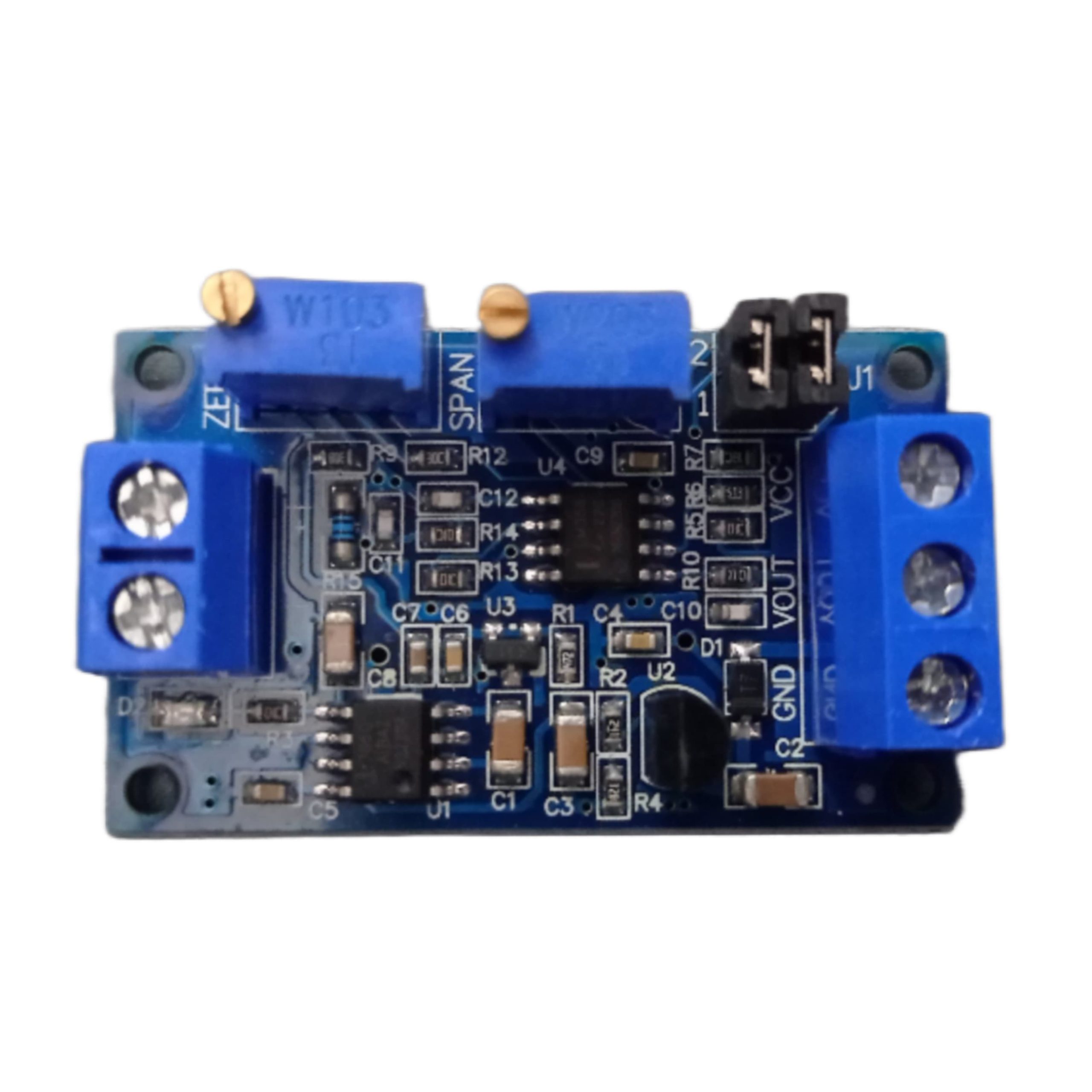
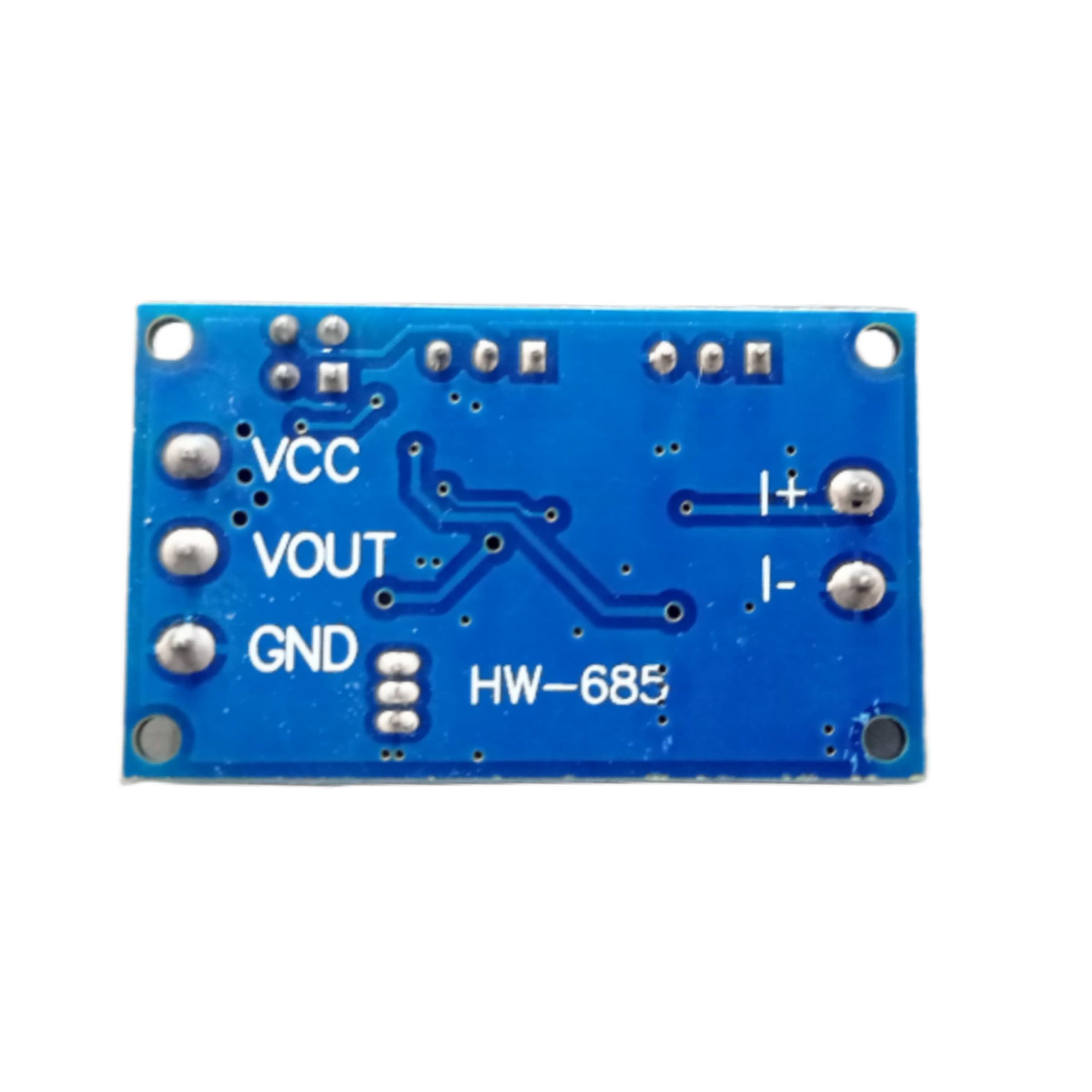
- The module according to the definition of wiring, power supply voltage 7-36V (if the output to 10V, the supply voltage must be greater than 12V).
- After power-up, the D2 indicator should be on, otherwise check the line connection. Board with reverse protection, the reverse does not burn.
- When the current input is the minimum (0mA or 4mA), adjust the ZERO potentiometer so that the VOUT output is the minimum (0.0V or other voltage).
- When the current input is at maximum (20mA), adjust the SPAN potentiometer so that the VOUT output is the maximum (3.3V or 5V or 10V, the output can be as low as 2.5V when the input is 4-20ma).
- According to your needs, through the jumper cap to select the appropriate range:
Jumper Settings for Output Voltage Range Input Signal: 4-20mA
- 1.0-2.5V: J1 1,2 pin are short circuit connected; 3, 4 pin are short circuit connected
- 2.0-3.3V: J1 1,2 pin are disconnected; 3, 4 pin are disconnected
- 3.0-5V: J1 1,2 pin are short circuit connected; 3, 4 pin are short circuit connected
- 4.0-10V: J1 1,2 pin are short circuit connected; 3, 4 pin are disconnected
Jumper Settings for Output Voltage Range Input Signal: 0-20mA:
- 1.0-3.3V: J1 1,2 pin are short circuit connected; 3, 4 pin are short circuit connected
- 2.0-5V: J1 1,2 pin are short circuit connected; 3, 4 pin are short circuit connected
- 3.0-10V: J1 1,2 pin are short circuit connected; 3, 4 pin are disconnected
For more related products: Click here
For more services: Click here

Reviews
There are no reviews yet.